Most performance enthusiasts understand that one of the most basic, yet effective means to increase horsepower in a performance engine is by raising the compression ratio. That doesn’t necessarily mean that you have to run out and buy a new set of pistons to accomplish the task. While a new set of flat-top pistons, for example, may provide added compression over existing dished units, there are other avenues that may be explored to achieve the same goal.
One of the easiest and most cost-effective methods of increasing engine compression may be done by simply replacing the existing head gaskets. Substituting steel shim gaskets, for example, in place of traditional composition-style units can raise the compression ratio slightly and reduce quench clearance by roughly .020”. Prior to swapping gaskets, deck clearance should be checked to ensure that it will remain adequate. Insufficient deck clearance can have dire consequences including damaged ring lands and broken rings. When replacing head gaskets, it’s important that all gasket surfaces are exceptionally clean during re-assembly while closely adhering to the manufacturer’s recommended torque sequencing and specifications. If MLS (Multi-Layer Steel) head gaskets are selected, it’s important to note that the block and heads must include the necessary RA (Roughness Average) finish in order to achieve the desired sealing surface.
Another common method of boosting engine compression is by milling the cylinder heads, which effectively reduces combustion chamber volume. It’s not uncommon for a cylinder head to be milled .040” or more depending upon the application. Prior to machining, it’s important to ensure that the heads in question are up to the task by consulting with a reputable engine shop, particularly if they’ve been machined previously. If the cylinder has had any significant amount milled from it, the intake side of head or intake manifold must be machined as well to a specific, calculated amount to ensure proper fit upon re-assembly. The intake side of the heads or manifold would also require machining if the block’s deck surface is machined substantially.
Reducing deck clearance may be done both to increase engine compression and to reduce quench area, a common practice on high-end racing engines where absolute maximum performance is desired. It’s not uncommon for a blueprinted race engine to feature deck clearances so tight that the pistons are almost touching the quench area during operation. Since the block must be bare prior to machining, it’s mandatory that the existing deck height is first checked on every cylinder during tear-down or by using a mocked-up rotating assembly to ensure that it’s plausible given the existing clearances.
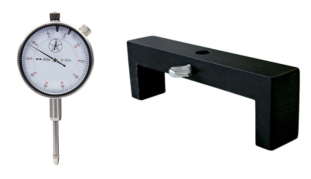
Measuring deck clearance and determining quench is relatively simple. The cylinder heads must be removed and the deck then thoroughly cleaned of gasket residue. A 1” travel dial indicator (Allstar Performance ALL96415) and special dial indicator stand (Proform PFM66798) may be used to measure clearance. The stand, large enough to span across a cylinder bore, is used to secure the dial indicator over the cylinder. The engine is then rotated until the desired cylinder is precisely at TDC (Top Dead Center), determined through use of the dial indicator and stand. The stand and dial indicator are then placed on the deck surface, adjacent to the top side of the cylinder and set to “0”. They are then carefully moved a short distance until the indicator drops into the cylinder and comes to rest on the piston. The first measurement is then recorded.

The stand and dial indicator are then placed on the opposite side of the cylinder, 180° from where the first measurement was attained. The dial indicator is again set to “0” on the deck prior to dragging it slowly onto the top of the piston. After both measurements have been obtained from the same cylinder, add the two together and split the difference for the result. For example, .001” + .003” = .004”, which divided by two = .002” actual deck clearance. The second measurement and calculation are done to take piston “rock” out of the equation. Finish by repeating the process on each cylinder.
Since the vast majority of engines have what is referred to as negative deck clearance where the top of the piston is below the deck at TDC, the indicator will drop slightly during deck clearance measurement. An engine with positive deck clearance features a piston that slightly protrudes from the cylinder at TDC, causing the dial indicator to rise above the deck to the piston when measured.
After all measurements have been taken, quench or piston-to-head clearance may be determined by simply adding head gasket thickness to deck clearance (example: .002” deck clearance + .038” head gasket thickness = .040” quench clearance). While many racing engines with steel rods are run with as little as .035”-.040” of quench, keep in mind that if the engine in question is a high-end powerhouse fit with aluminum rods, it will require significantly more clearance due to the expansion characteristics of aluminum.
In the event that a significant amount of material is removed from the block or heads to meet the desired results, piston-to-valve clearance, rocker arm geometry and hydraulic lifter preload, if applicable, should be carefully checked and corrected as necessary during engine re-assembly. It’s also recommended to consult with a trusted machine shop professional before moving forward with any project that involves extensive engine modifications.
While upping the engine compression ratio traditionally offers more torque and horsepower, it’s important to note that cylinder pressures also typically rise as a result, increasing the chance of detonation and potential need to switch to a higher octane fuel.